

Catalog
| Items |
 /Asset/a1151.jpg /Asset/a1151.jpg SUF 60 120 NE Ultra Force™ Up to 96% Efficient Commercial Gas Water Heaters |
/Asset/a1151.jpg SUF 60 120 NE-A Ultra Force™ Up to 96% Efficient Commercial Gas Water Heaters |
/Asset/a1151.jpg SUF 100 150 NE Ultra Force™ Up to 96% Efficient Commercial Gas Water Heaters |
/Asset/a1151.jpg SUF 100 150 NE-A Ultra Force™ Up to 96% Efficient Commercial Gas Water Heaters |
/Asset/a1151.jpg SUF 100 199 NE Ultra Force™ Up to 96% Efficient Commercial Gas Water Heaters |
|||||
| Manufacturer | State® | |||||||||
| Standard Type | Non-ASME | ASME | Non-ASME | ASME | Non-ASME | |||||
| Input Power | 120000 BTU/hr35 kW | 120000 BTU/hr35 kW | 150000 BTU/hr44 kW | 150000 BTU/hr44 kW | 199900 BTU/hr58 kW | |||||
| Thermal Efficiency | 95 % | |||||||||
| Capacity | 60 U.S. gal227 L | 60 U.S. gal227 L | 100 U.S. gal379 L | 100 U.S. gal379 L | 100 U.S. gal379 L | |||||
| Recovery at 30 ºF Temperature Rise | 461 gal/h | 461 gal/h | 576 gal/h | 576 gal/h | 767 gal/h | |||||
| Recovery at 17 ºC Temperature Rise | 1744 L/h | 1744 L/h | 2179 L/h | 2179 L/h | 2904 L/h | |||||
| Recovery at 40 ºF Temperature Rise | 345 gal/h | 345 gal/h | 432 gal/h | 432 gal/h | 575 gal/h | |||||
| Recovery at 22 ºC Temperature Rise | 1308 L/h | 1308 L/h | 1635 L/h | 1635 L/h | 2178 L/h | |||||
| Recovery at 50 ºF Temperature Rise | 276 gal/h | 276 gal/h | 345 gal/h | 345 gal/h | 460 gal/h | |||||
| Recovery at 28 ºC Temperature Rise | 1046 L/h | 1046 L/h | 1308 L/h | 1308 L/h | 1743 L/h | |||||
| Recovery at 60 ºF Temperature Rise | 230 gal/h | 230 gal/h | 288 gal/h | 288 gal/h | 384 gal/h | |||||
| Recovery at 33 ºC Temperature Rise | 872 L/h | 872 L/h | 1090 L/h | 1090 L/h | 1452 L/h | |||||
| Recovery at 70 ºF Temperature Rise | 197 gal/h | 197 gal/h | 247 gal/h | 247 gal/h | 329 gal/h | |||||
| Recovery at 39 ºC Temperature Rise | 747 L/h | 747 L/h | 934 L/h | 934 L/h | 1245 L/h | |||||
| Recovery at 80 ºF Temperature Rise | 173 gal/h | 173 gal/h | 216 gal/h | 216 gal/h | 288 gal/h | |||||
| Recovery at 44 ºC Temperature Rise | 654 L/h | 654 L/h | 817 L/h | 817 L/h | 1089 L/h | |||||
| Recovery at 90 ºF Temperature Rise | 154 gal/h | 154 gal/h | 192 gal/h | 192 gal/h | 256 gal/h | |||||
| Recovery at 50 ºC Temperature Rise | 581 L/h | 581 L/h | 726 L/h | 726 L/h | 968 L/h | |||||
| Recovery at 100 ºF Temperature Rise | 138 gal/h | 138 gal/h | 173 gal/h | 173 gal/h | 230 gal/h | |||||
| Recovery at 56 ºC Temperature Rise | 523 L/h | 523 L/h | 654 L/h | 654 L/h | 871 L/h | |||||
| Recovery at 110 ºF Temperature Rise | 126 gal/h | 126 gal/h | 157 gal/h | 157 gal/h | 209 gal/h | |||||
| Recovery at 61 ºC Temperature Rise | 476 L/h | 476 L/h | 594 L/h | 594 L/h | 792 L/h | |||||
| Recovery at 120 ºF Temperature Rise | 115 gal/h | 115 gal/h | 144 gal/h | 144 gal/h | 192 gal/h | |||||
| Recovery at 67 ºC Temperature Rise | 436 L/h | 436 L/h | 545 L/h | 545 L/h | 726 L/h | |||||
| Recovery at 130 ºF Temperature Rise | 106 gal/h | 106 gal/h | 133 gal/h | 133 gal/h | 177 gal/h | |||||
| Recovery at 72 ºC Temperature Rise | 402 L/h | 402 L/h | 503 L/h | 503 L/h | 670 L/h | |||||
| Recovery at 140 ºF Temperature Rise | 99 gal/h | 99 gal/h | 123 gal/h | 123 gal/h | 164 gal/h | |||||
| Recovery at 78 ºC Temperature Rise | 374 L/h | 374 L/h | 467 L/h | 467 L/h | 622 L/h | |||||
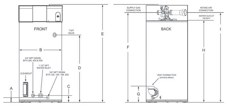
| Schematic |
 |
|||||||||
| Dimension A | 3 in7.62 cm | |||||||||
| Dimension B | 27.75 in70.5 cm | |||||||||
| Dimension C | 6.3 in16 cm | |||||||||
| Dimension D | 35 in88.9 cm | 35 in88.9 cm | 55.5 in141 cm | 55.5 in141 cm | 55.5 in141 cm | |||||
| Dimension E | 55.5 in141 cm | 55.5 in141 cm | 75.5 in191.8 cm | 75.5 in191.8 cm | 75.5 in191.8 cm | |||||
| Dimension F | 48 in121.9 cm | 48 in121.9 cm | 68.5 in174 cm | 68.5 in174 cm | 75.5 in191.8 cm | |||||
| Dimension G | 11 in27.9 cm | |||||||||
| Dimension H | 42 in106.7 cm | 42 in106.7 cm | 63 in160 cm | 63 in160 cm | 63 in160 cm | |||||
| Dimension I | 47.5 in120.6 cm | 47.5 in120.6 cm | 69 in175.3 cm | 69 in175.3 cm | 69 in175.3 cm | |||||
| Standard Approximate Shipping Weight | 460 lb208 kg | 460 lb208 kg | 555 lb252 kg | 555 lb252 kg | 555 lb252 kg | |||||
| ASME Approximate Shipping Weight | 490 lb222 kg | 490 lb222 kg | 595 lb270 kg | 595 lb270 kg | 595 lb270 kg | |||||
| Minimum Supply Natural Gas Line Size (N.P.T.) | 1/2 in | 1/2 in | 3/4 in | 3/4 in | 3/4 in | |||||
| Minimum Supply Propane Gas Line Size (N.P.T.) | 1/2 in | 1/2 in | 3/4 in | 3/4 in | 3/4 in | |||||
| One 90º Elbows for Maximum 3" Vent Pipe | 45 ft13.7 m | |||||||||
| Two 90º Elbows for Maximum 3" Vent Pipe | 40 ft12.2 m | |||||||||
| Three 90º Elbows for Maximum 3" Vent Pipe | 35 ft10.7 m | |||||||||
| Four 90º Elbows for Maximum 3" Vent Pipe | 30 ft9.1 m | |||||||||
| One 90º Elbows for Maximum 4" Vent Pipe | 115 ft35 m | |||||||||
| Two 90º Elbows for Maximum 4" Vent Pipe | 110 ft33.5 m | |||||||||
| Three 90º Elbows for Maximum 4" Vent Pipe | 105 ft32 m | |||||||||
| Four 90º Elbows for Maximum 4" Vent Pipe | 100 ft30.5 m | |||||||||
| Five 90º Elbows for Maximum 4" Vent Pipe | 95 ft29 m | |||||||||
| Six 90º Elbows for Maximum 4" Vent Pipe | 90 ft27.4 m | |||||||||
| One 90º Elbows for Maximum 6" Vent Pipe | ||||||||||
| Two 90º Elbows for Maximum 6" Vent Pipe | ||||||||||
| Three 90º Elbows for Maximum 6" Vent Pipe | ||||||||||
| Four 90º Elbows for Maximum 6" Vent Pipe | ||||||||||
| Five 90º Elbows for Maximum 6" Vent Pipe | ||||||||||
| Six 90º Elbows for Maximum 6" Vent Pipe | ||||||||||
| Water Connection | 1-1/2 in | |||||||||
| Type | Liquid Propane Gas Natural Gas | |||||||||
| Style | Ultra Force™ | |||||||||
| Size | C | |||||||||
| Industry Standards | AHRI Certified® ASHRAE/IESNA 90.1 ASME Certified CSA® Certified Energy Star UL® Listed | |||||||||
| General Information |
Installation Considerations
|
|||||||||
| Features |
Down-Fired Low NOx Power Burner Design
|
|||||||||
| Other Features |
Commercial Grade Glasslined Tank & Heat Exchanger for Long-Term Protection Against Corrosion
|
|||||||||
| Testing and Certifications |
ASME Construction
CSA® Certified and ASME Rated T&P Relief Valve All models are ENERGY STAR® Qualified |
|||||||||
| Warranty |
|
|||||||||
| Note |
Recovery capacities are based on heater performance at 95% and 96% thermal efficiency. Maximum gas supply pressure: 10.5" W.C. natural gas 14" W.C. propane. Electrical requirements: 120/60 Hz VAC, Blower 2.2 Amps FL, Igniter 4.0 Amps. Minimum clearance to remove top cover. Additional clearances recommended in case service is needed. Maximum number of 90º elbows allowed for the vent (exhaust) pipe is four (4) when installing 3 inch pipe and six (6) when installing 4 inch pipe. Maximum number of 90º elbows allowed for intake air pipe is four (4) when installing 3 inch pipe and six (6) when installing 4 inch pipe. Two (2) 45º elbows equal one (1) 90º elbow. Center line of water outlet on top of the water heaters is approximately 7 inches from the front edge of the water heater. |
Recovery capacities are based on heater performance at 95% and 96% thermal efficiency. Add "A" to model number when ordering ASME. Optional on all Models. Maximum gas supply pressure: 10.5" W.C. natural gas 14" W.C. propane. Electrical requirements: 120/60 Hz VAC, Blower 2.2 Amps FL, Igniter 4.0 Amps. Minimum clearance to remove top cover. Additional clearances recommended in case service is needed. Maximum number of 90º elbows allowed for the vent (exhaust) pipe is four (4) when installing 3 inch pipe and six (6) when installing 4 inch pipe. Maximum number of 90º elbows allowed for intake air pipe is four (4) when installing 3 inch pipe and six (6) when installing 4 inch pipe. Two (2) 45º elbows equal one (1) 90º elbow. Center line of water outlet on top of the water heaters is approximately 7 inches from the front edge of the water heater. |
Recovery capacities are based on heater performance at 95% and 96% thermal efficiency. Maximum gas supply pressure: 10.5" W.C. natural gas 14" W.C. propane. Electrical requirements: 120/60 Hz VAC, Blower 2.2 Amps FL, Igniter 4.0 Amps. Minimum clearance to remove top cover. Additional clearances recommended in case service is needed. Maximum number of 90º elbows allowed for the vent (exhaust) pipe is four (4) when installing 3 inch pipe and six (6) when installing 4 inch pipe. Maximum number of 90º elbows allowed for intake air pipe is four (4) when installing 3 inch pipe and six (6) when installing 4 inch pipe. Two (2) 45º elbows equal one (1) 90º elbow. Center line of water outlet on top of the water heaters is approximately 7 inches from the front edge of the water heater. |
|||||
|
|
||||||||||